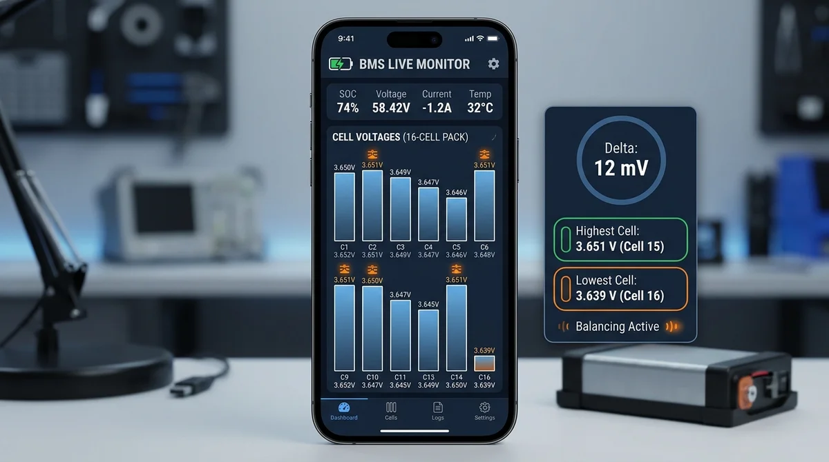
- What is ΔV (Delta): Delta voltage represents the mathematical difference between the highest voltage cell (Vmax) and lowest voltage cell (Vmin) in a series string.
- Healthy Thresholds: For LiFePO4 packs, a healthy resting delta is under 15 mV. Any variance exceeding 50 mV under resting conditions demands immediate balancing.
- Preventing Sudden Cutoffs: A single out-of-balance cell hitting the low-voltage cutoff threshold will cause the BMS to disconnect the entire pack, even if the total battery gauge reads 40% SOC!
Table of Contents
- 1. What is Cell Voltage Delta (ΔV) in Battery Packs?
- 2. How BAT-BMS Tracks and Displays Millivolt (mV) Variance
- 3. Benchmark Guide: What is an Acceptable vs. Dangerous Delta?
- 4. Passive Bleed Resistors vs. Active Capacitive Balancing
- 5. Recommended Balancing Settings in BAT-BMS for LiFePO4 & NMC
- 6. How to Identify Degraded or High-Resistance Cells
- 7. Frequently Asked Questions
- 8. Sources & References
1. What is Cell Voltage Delta (ΔV) in Battery Packs?
In any multi-cell lithium battery pack (such as a 16S 48V LiFePO4 pack or a 20S 72V NMC setup), individual cells are connected in series to achieve the target operating voltage. However, because manufacturing variations, thermal gradients across the pack, and differing self-discharge rates are inevitable, individual cells charge and discharge at slightly different speeds.
The Cell Voltage Delta (ΔV) is defined as:
When ΔV grows excessive, the weakest cell reaches the safety threshold prematurely during discharge, triggering an undervoltage cutoff (UVP) and halting your vehicle, even though the other 15 cells may still contain substantial energy.
2. How BAT-BMS Tracks and Displays Millivolt (mV) Variance
The BAT-BMS app samples individual cell sense wires at 500-millisecond intervals. On the primary dashboard screen, the interface highlights:
- Green Bar: Highest voltage cell (Vmax), showing its cell index number.
- Red / Orange Bar: Lowest voltage cell (Vmin), denoting the bottleneck cell.
- Center Badge: Real-time delta readout (e.g.,
Δ 0.012V / 12mV). - Flashing Balance Icon (⚖): Indicates that the onboard passive bypass resistors are currently bleeding current from high-voltage cells.
3. Benchmark Guide: What is an Acceptable vs. Dangerous Delta?
Because LiFePO4 cells have an extraordinarily flat voltage discharge curve between 20% and 80% SOC, interpreting delta values requires context:
| Delta Range (mV) | Battery State | Assessment & Recommended Action |
|---|---|---|
| 0 – 15 mV | Resting or Nominal Load | Optimal Health — Perfectly balanced string. |
| 15 – 35 mV | Heavy Acceleration / High Discharge | Normal — Dynamic delta caused by internal resistance differences. |
| 35 – 70 mV | Resting after Full Charge | Moderate Imbalance — Leave pack connected to charger for 4–6 hours of passive balancing. |
| 70 – 150+ mV | Resting at Nominal SOC | Severe Imbalance — Defective cell or high-resistance balance wire terminal. |
4. Passive Bleed Resistors vs. Active Capacitive Balancing
Standard Grenergy BMS units utilize passive balancing. Inside the casing, small surface-mount resistors (typically 39Ω to 68Ω) bleed away excess charge from the highest cells at approximately 40mA to 60mA, dissipating that energy as heat.
While effective for minor maintenance on healthy packs, passive balancing is slow: correcting a 100mV imbalance on a large 100Ah cell pack can take upwards of 48 continuous hours. For heavy-duty commercial vehicles, pairing the Grenergy BMS with a secondary 1A to 5A active inductive/capacitive balancer transfers energy directly from higher cells to lower cells with 92% efficiency, keeping delta below 10mV under heavy duty cycles.
5. Recommended Balancing Settings in BAT-BMS for LiFePO4 & NMC
In the BAT-BMS configuration panel, adjust the following parameters to ensure optimal balance logic:
- Balance Start Voltage: Set to
3.40Vfor LiFePO4 (or4.10Vfor NMC). Crucial: Never configure balancing to operate below 3.35V on LiFePO4, as balancing along the flat portion of the curve causes false drift! - Balance Trigger Delta: Set to
15mV(0.015V). Setting it lower (e.g. 5mV) leads to constant resistor switching and unnecessary heat generation. - Balancing Mode: Select "Charge Only" or "Charge and Standby". Avoid balancing during active discharge, as dynamic load sag skews accurate reading.
6. How to Identify Degraded or High-Resistance Cells
Using the real-time graphing tab in BAT-BMS, watch how cell voltages react when the throttle is applied:
- Healthy Cell: Voltage sags uniformly by 50–80mV under a 30A load, then recovers instantly when the throttle is released.
- High Internal Resistance (IR) Cell: Voltage plunges by 250–400mV under load, then bounces back sharply. Indicates corrosion at busbar terminals or aging cell foil.
- Capacity Degraded Cell: Charges to 3.65V faster than all other cells, and drops to 2.80V faster than all others. Requires individual cell replacement.
7. Frequently Asked Questions
Yes. As long as the charger is connected and providing float current, the BMS will continuously run passive balancing on cells exceeding the configured threshold.
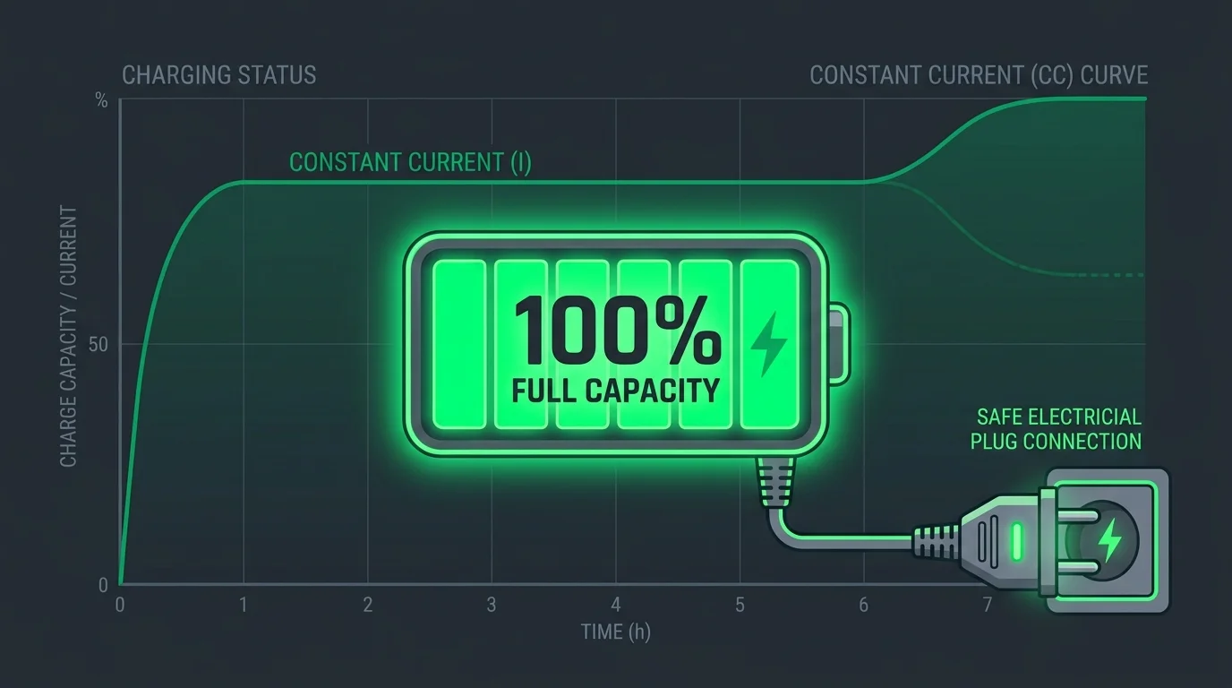
This is standard behavior known as the "charge knee". Above 3.45V per cell, tiny capacity differences translate into large voltage jumps. Allow the charger to absorb at constant voltage until the BMS balance bleeders equalize the pack.
8. Sources & References
- Journal of Energy Storage: "Cell Balancing Methodologies in Commercial Electric Vehicle Packs".
- Shenzhen Grenergy Technical Manual: Passive Balancing Circuit Topologies.
- LiFePO4 Electrochemical Cell Health & Variance Management, IEEE 2025.